A Practical Guide to Shell-and-Tube Heat Exchanger Fluid Allocation
A Practical Guide to Shell-and-Tube Heat Exchanger Fluid Allocation
Fluid allocation in a shell-and-tube heat exchanger is one of the most consequential early design decisions in process engineering. Poor allocation can dramatically increase cost, reduce reliability, and introduce operational hazards.
Incorrect allocation frequently drives:
- Higher shell thickness (cost ↑)
- Exotic alloy requirements (material cost ↑)
- Cleaning downtime (OPEX ↑)
- Thermal performance losses (area ↑)
This guide compiles the fundamental rules of thumb used by major operators and EPCs for reliable, low-cost heat exchanger design.
Why Getting Fluid Allocation Wrong Costs You Millions
A single wrong decision on tube-side vs shell-side allocation can add hundreds of thousands to millions of dollars in total installed cost and can cause long-term maintenance penalties.
Real examples include:
- A refinery that placed crude oil (fouling + corrosive) on the shell side → required expensive alloy cladding.
- A gas plant that placed high-pressure refrigerant on the shell side → forced uprating the entire shell.
- A polyester plant that put viscous slurry on the tube side → required frequent shutdowns for cleaning.
Correct allocation can avoid 95% of these issues with a simple set of heuristics.
Master Decision Table (Print & Pin Above Your Desk)
| Fluid Characteristic | Preferred Side | Primary Reason (Cost/Safety/Performance) | Typical Savings |
|---|---|---|---|
| Highest pressure (> 20 barg) | Tube side | Tubes + channel cheaper to design for high pressure | 15-45 % |
| Most corrosive / toxic | Tube side | Limits exotic alloy to tubes, tubesheet, and channel | 30-70 % |
| Most fouling / scaling / dirty | Tube side | Mechanical cleaning + higher velocity | 40-80 % |
| Highest temperature (> 350 °C) | Tube side | Protects shell from high metal temperature | 10-25 % |
| Viscous fluid (μ > 50 cP) | Shell side | Better heat transfer at low Re; turbulence from baffles | 20-40 % |
| Lowest volumetric flow rate | Shell side | Avoids excessive tube-side pressure drop | 15-35 % |
| Condensing vapor | Shell side | Gravity drainage + easier venting | 25-50 % |
| Boiling fluid | Shell side | Prevents vapor lock + improves stability | Critical |
| Contains non-condensables | Tube side | Positive venting at tube outlet | Essential |
| Risk of freezing on cold startup | Shell side | Freezing in shell is survivable; frozen tubes rupture | Avoid failure |
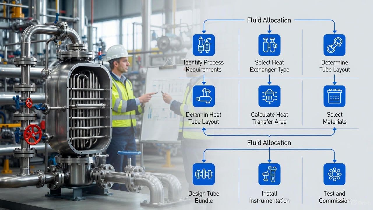
Quick 60-Second Allocation Flowchart

Real Industry Examples That Paid Off
| Project / Location | Service | Allocation Decision | Result / Savings |
|---|---|---|---|
| NGL Fractionation | High-pressure propane | High-pressure fluid → tubes | Large capital savings |
| Ethylene Cracker | Corrosive, fouling crude | Crude → tubes; cooling water → shell | Exotic alloy minimized |
| PTA Plant | Slurry stream (high fouling) | Slurry → tubes (rotatable bundle) | Major extension in cleaning interval |
| Offshore Platform | Thermal oil reboiler (condensing) | Condensing service → shell | Lower area + stable operation |
| Caustic Soda Plant | 50% NaOH (viscous + corrosive) | NaOH → shell; steam → tubes | Lower ΔP + cheaper metallurgy |
Pro Tips Most Junior Engineers Miss
- Never put both high pressure AND corrosive fluids on the shell side - metallurgy cost becomes extreme.
- Cooling water usually belongs on the tube side - easier cleaning and higher velocity minimize fouling.
- Vacuum streams typically go on the shell side - avoids thick-wall tubes.
- Rotatable U-tube bundles dramatically reduce cleaning costs when the fouling fluid must be on the tube side.
Key Engineering Notes
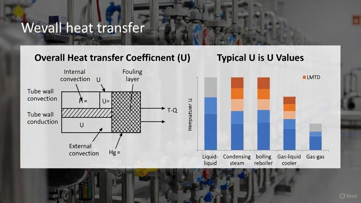
Governing Equations
Overall heat-transfer coefficient:
Tube-side velocity requirement:
Shell-side Reynolds number (Bell-Delaware):
Where:
- = equivalent diameter
- = mass velocity across tube bundle
These relationships explain why viscous or low-flow-rate fluids often perform better on the shell side.
Design Example (Worked)
Service: Hot fouling hydrocarbon → cooled by cooling water
Task: Choose tube vs shell allocation
Step 1 - Compare fouling
Hydrocarbon fouling factor:
Cooling water fouling factor:
Decision: Put fouling hydrocarbon on tube side.
Step 2 - Material
Hydrocarbon requires 316SS, water requires CS.
Tube-side allocation confines 316SS to tubes only → large cost savings.
Step 3 - Maintainability
Tube-side mechanical cleaning possible → further OPEX savings.
Final allocation: Hydrocarbon → tubes; cooling water → shell.
Final Checklist Before Freezing the P&ID
- Highest pressure → tubes
- Most corrosive or toxic → tubes
- Most fouling → tubes (or use rotatable bundle)
- Phase-change service → shell
- Viscous or lowest flow → shell
- Non-condensables → tubes
- Freezing risk → shell
- Cooling water (unless seawater + titanium) → tubes