Overall Heat Transfer Coefficient U – Practical Design Guide
A Practical Guide to Overall Heat Transfer Coefficient (U) and Heat Exchanger Design Rules of Thumb
The thermal design of heat exchangers in chemical, petrochemical, and power plants revolves around one central parameter: the overall heat transfer coefficient, .
The fundamental design equation remains:
where:
- = heat duty
- = overall heat transfer coefficient (W/m²·K)
- = heat transfer area (usually based on tube outside surface)
- = corrected mean temperature difference (typically )
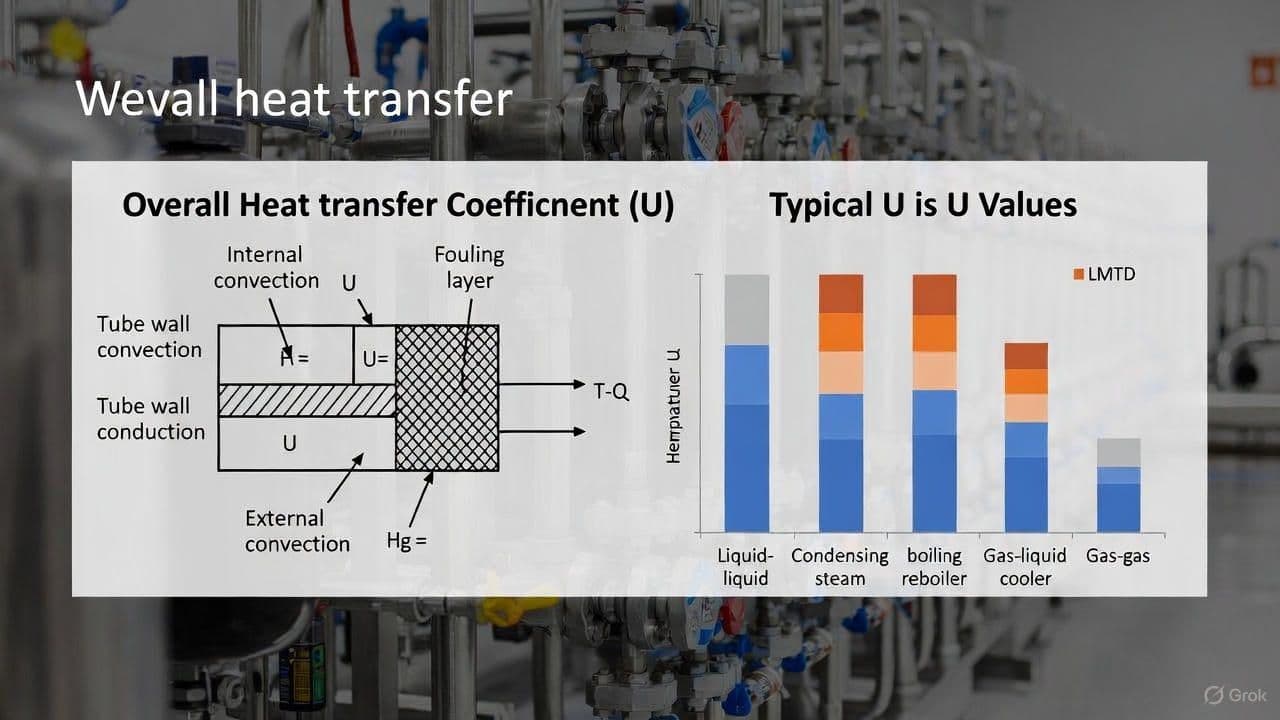
1. What the Overall Heat Transfer Coefficient Really Includes
For a tubular exchanger, the exact resistance equation (with based on outside area) is:
Where:
- , = shell-side and tube-side film coefficients (W/m²·K)
- , = shell-side and tube-side fouling resistances (m²·K/W)
- = tube wall thermal conductivity (W/m·K)
- , = tube outside and inside diameters (m)
In preliminary design, the wall and area-correction terms are relatively small (≈3-8 %) for common carbon/stainless tubes. Many engineers use a simplified resistance sum and then verify details later in rating.
2. Fouling Factors - Current Best Practice
TEMA 10th edition (2019) and most modern company standards have reduced recommended fouling factors. Over-specifying fouling is one of the most common causes of oversized, expensive exchangers.
Table 1 - Typical Fouling Resistances and Equivalent
| Service | Typical Fouling Resistance (m²·K/W) | Equivalent (W/m²·K) | Notes |
|---|---|---|---|
| Cooling water (clean, treated) | 0.00009 - 0.00018 | 5,500 - 11,000 | Good treatment, m/s |
| Cooling water (brackish/seawater) | 0.00018 - 0.00035 | 2,850 - 5,500 | Check for scaling, biofouling |
| Treated boiler feedwater | 0.00002 - 0.00009 | >10,000 | Essentially clean |
| Steam (clean, non-oil-bearing) | 0.00001 - 0.00005 | >20,000 | Often taken as ~0 in prelim design |
| Light hydrocarbons | 0.00010 - 0.00020 | 5,000 - 10,000 | Deposits depend on composition |
| Heavy oils, crude fractions | 0.00040 - 0.00080 | 1,250 - 2,500 | Coking / asphaltene risk |
| Gases (dry) | ~0.00010 | ~10,000 | Dust can increase fouling |
Rule of thumb :
Avoid using more than 0.00035 m²·K/W total fouling unless plant history proves it is needed.
3. Realistic Overall Heat Transfer Coefficients
These values reflect typical clean vs design (with fouling) for shell-and-tube exchangers.
Table 2 - Typical Overall Values by Service
| Service | Typical Clean (W/m²·K) | Typical Design (incl. fouling) | Notes |
|---|---|---|---|
| Water - Water | 1,400 - 2,500 | 800 - 1,500 | Plate exchangers can exceed 4,000 |
| Water - Light oil ( cP) | 800 - 1,400 | 350 - 900 | |
| Water - Medium oil (5-50 cP) | 400 - 800 | 200 - 500 | |
| Water - Heavy oil ( cP) | 100 - 400 | 60 - 250 | Strongly viscosity-limited |
| Steam - Water (condensing steam) | 4,000 - 8,000 | 1,500 - 4,000 | Condensing on shell |
| Steam - Heavy oil (condensing) | 800 - 2,000 | 400 - 1,200 | Oil-side limits |
| Organic - Organic liquids | 500 - 1,200 | 250 - 800 | |
| Gas - Gas (1-10 bar) | 50 - 250 | 25 - 150 | Low is normal |
| Gas - Liquid (process gas cooler) | 100 - 700 | 50 - 400 | Depends heavily on gas side |
| Refrigerant evaporating - Water | 1,500 - 3,500 | 800 - 2,000 | Chillers, evaporators |
| Air-cooled exchangers (process liquid) | 400 - 800 | 300 - 600 | Based on bare tube area |
Sanity check: If your calculated is < 50 % or > 200 % of these ranges, revisit:
- Correlation choice
- Velocity and flow regime
- Fouling assumptions
- Geometry (very short or very long tubes, unusual layouts)
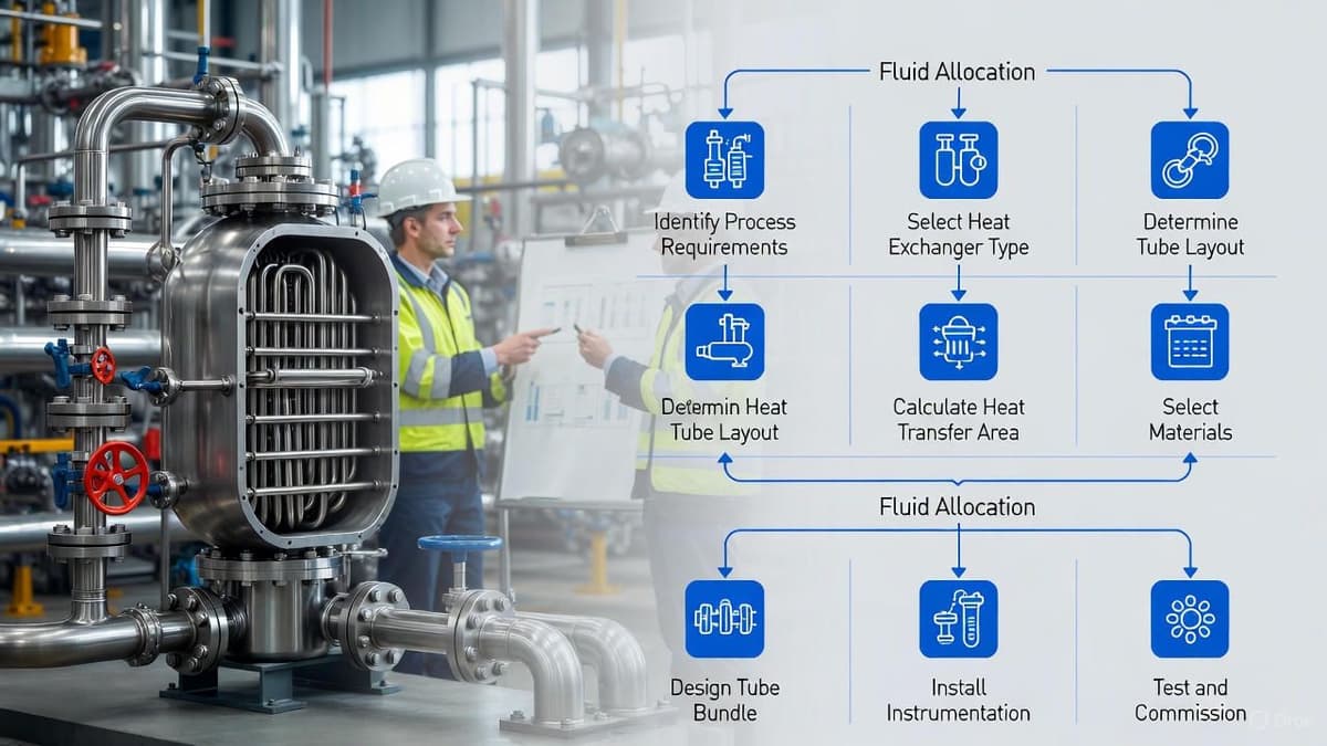
4. Golden Rules of Thumb - Fluid Allocation
Where to put each fluid (shell vs tube) has a big impact on cost, performance, and maintainability.
Table 3 - Fluid Allocation Guidance
| Condition | Preferred Side | Reason |
|---|---|---|
| Corrosive fluid | Tube side | Cheaper to build tubes & channel in alloy than entire shell |
| High-pressure fluid (> 70 barg) | Tube side | Tubes and channel withstand pressure more economically |
| Fouling / scaling fluid | Tube side | Easier mechanical cleaning, higher allowable velocity |
| Very viscous fluid | Shell side | Cross-flow over baffles improves turbulence & |
| Condensing vapor | Shell side | Gravity drainage, better condensate handling, easier subcooling |
| Boiling fluid | Often shell side (kettle) or tube side (thermosiphon) | Depends on configuration & control |
| Low allowable pressure drop | Shell side | Larger flow area, lower velocity |
5. Velocity & Pressure-Drop Rules of Thumb
Velocities must balance heat transfer performance, erosion risk, and pumping power.
Table 4 - Typical Velocities and Targets
| Fluid / Side | Recommended Velocity | Typical Allowance |
|---|---|---|
| Cooling water (tube side) | 1.5 - 2.5 m/s | 0.5 - 1.0 bar |
| Process water (tube side) | 1.2 - 2.0 m/s | |
| Light hydrocarbons (tubes) | 1.5 - 3.0 m/s | |
| Viscous liquids (> 50 cP) | < 1.0 m/s | Keep shear & manageable |
| Shell-side liquids | 0.5 - 1.0 m/s (crossflow zone) | 0.3 - 0.7 bar |
| Saturated vapor | Limit | Erosion / noise control |
Higher velocities → higher , but also:
- Higher pressure drop
- More erosion risk (especially with solids or flashing)
- Possible vibration issues in tubes
6. Temperature Approach & LMTD Correction Factor
For countercurrent flow, the Log Mean Temperature Difference is:
Where:
In shell-and-tube exchangers with multiple passes, a correction factor is applied:
Practical Targets
- Minimum economic approach (process-process): typically 15-25 °C
- Water coolers: approach (hot in - water out) often 8-12 °C
- Refrigeration chillers: 3-6 °C (tighter for energy efficiency)
LMTD correction factor :
- Aim for for most shell-and-tube designs
- For simple 1-2 or 2-4 exchangers, is often 0.90-0.95
- If , consider:
- Additional shells in series
- Different pass arrangement
- Plate heat exchanger or other configuration
Temperature cross (when ):
- Can be feasible in multi-shell arrangements
- Requires careful LMTD + evaluation; not recommended in a single simple S&T without a detailed check
7. Quick Preliminary Sizing Example (Updated)
Objective: Cool 250 t/h of lube oil from 80 °C → 50 °C using cooling water 32 °C → 42 °C.
Assume:
- MW (from detailed enthalpy balance; not shown here)
Step 1 - Temperature Differences
LMTD:
Assume a 1-shell, 2-tube-pass exchanger:
- From standard LMTD correction charts →
So:
Step 2 - Choose Trial
From Table 2, for oil-water service:
- Design in the range 350-900 W/m²·K
Take a conservative .
Step 3 - Area Estimate
This is a realistic first-pass result:
- You would then pick tube size (e.g. 19 mm OD, 6-8 m length), count, passes, and shell size
- Next step: compute detailed , , fouling effects and compare the calculated with this trial value (450 W/m²·K)
- Adjust layout or velocities as needed and iterate
8. Final Sanity-Check Checklist
Use this list before accepting any heat exchanger design (in-house or vendor):
- Is design within ±50 % of typical values for the service?
- Tube-side liquid velocities in the 1.2-2.5 m/s range (unless special case)?
- Total fouling resistance ≤ 0.00035 m²·K/W unless plant data justifies more?
- LMTD correction factor ?
- No problematic temperature cross in a single-shell unit?
- Pressure drops compatible with pump/compressor head and control valves?
- Fluid allocation consistent with corrosion, fouling, and pressure guidelines?
Mastering these numbers and rules means you will:
- Avoid chronic under-performing exchangers
- Avoid over-designed, unnecessarily expensive units
- Speak the same language as vendors, licensors, and operations teams
The rest is refinement with HTRI, Aspen EDR, or vendor software - but good engineering judgement starts with a solid feel for , fouling, and these rules of thumb.